
Stepper motor
Moderators:R!C0, JonMan, RickS
Hi I am wanting to run a idle stepper motor on my EM36 but i am unsure how to wire it up
Its a pug/citroen valve and is 4 wire type like the one in the link
http://media3.picsearch.com/is?vQaBvNsj ... qgJJsuTnGw
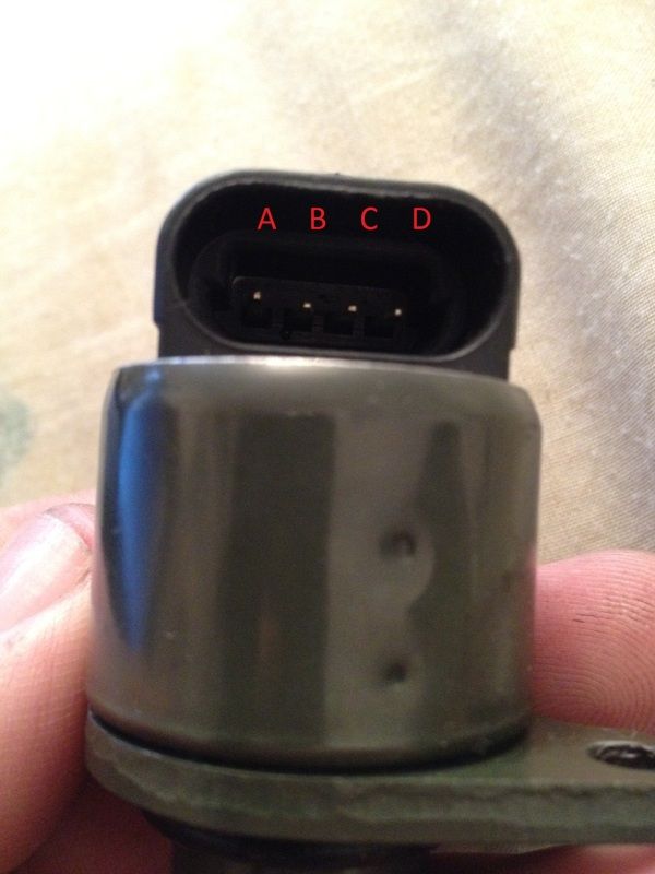
It has 4 pins labled ABCD
Pins A and D are linked and B and C are linked by a coil/windings as far as i can see and the resistance is aprox 50 ohms
Can any one point me in the correct direction to wire it up
Thanks
Si
Its a pug/citroen valve and is 4 wire type like the one in the link
http://media3.picsearch.com/is?vQaBvNsj ... qgJJsuTnGw
It has 4 pins labled ABCD
Pins A and D are linked and B and C are linked by a coil/windings as far as i can see and the resistance is aprox 50 ohms
Can any one point me in the correct direction to wire it up
Thanks
Si

Re: Stepper motor
Hi Si,
Do I understand that the stepper motor you have is a Marelli or 'like' a Marelli?
If it is, would you please forward me the Marelli serial number (Something like MARELLI:230016079087 2300160) if you are able.
Many thanks,
RickS
Do I understand that the stepper motor you have is a Marelli or 'like' a Marelli?
If it is, would you please forward me the Marelli serial number (Something like MARELLI:230016079087 2300160) if you are able.
Many thanks,
RickS
Re: Stepper motor
..... the reason I need this info is that the EM36 is designed for Uni-Polar steppers (5-6 wire) and a 4 wire system (Bi-Polar) may need to be 'pulled -up'.
Regards,
RickS
Regards,
RickS
Re: Stepper motor
Hi Rick
I havent been able to find the full number so far as mine isnt a genuine idle valve i will try see the number of a friends tomorrow i have some other numbers that may help?
VDO A96144
Magneti Marelli B17/00
CITROËN-PEUGEOT 1920.2Q
CITROËN-PEUGEOT 19202Q
HELLA 6NW 009 141-251
Magneti Marelli B1700
Thanks
Si
Re: Stepper motor
That will probably do Si. Thanks.
I'll try to check it out this morning.
RickS
I'll try to check it out this morning.
RickS
Re: Stepper motor
The EM36 will have trouble in controlling a 4 wire, Bi-Polar Stepper Motor, the EM36 being designed for a 5/6 wire Uni-Polar version.
As the Bi-Polar (4 wire) Stepper Motor coils lack the centre taps of the Uni-Polar (5/6 wire), the Bi-Polar Motor requires a different way of being controlled. It needs to be able to reverse the current flow through the coils by alternating polarity of the terminals.
The Bi-Polar Stepper Motor has 2 coils and although these coils are identical, they are not electrically connected.
To be able to reverse the polarity of the voltage across either coil, and to be able to energize these coils in sequence, you will need a device/circuit called an H-Bridge, two components of which would be the 'pull-up' resistors I mentioned earlier. This will allow the current to be reversed through the coil by closing the appropriate software switches. If you get in touch with OMEX at:-
http://www.omextechnology.co.uk
I believe that they have a suitable device and although it doesn't appear on their website, it's worth giving them a call if you're going to go down this route.
Follow this link for a better and fuller explanation of why you would need this:-
http://en.wikipedia.org/wiki/Stepper_motor
I will get some similar information posted in the FAQ forum for others
Regards,
RickS
Re: Stepper motor
Cheers Rick i will get on to Omex tomorrow
Thanks
Si
Thanks
Si
Re: Stepper motor
They should be able to help you with the ECU 'connect-ability' as theirs are modelled on ours.
Regards,
RickS
Regards,
RickS
Re: Stepper motor
Right guys dug this one back up
When I initially contacted Omex I got no responce and I was in abit of a rush so I continued to use my 2 wire bosch PWM idle valve this valve has now had it and wont work below 80% duty which we found out when mapping for a new inlet, so im back on to using the standard valve as my new inlet manifold is designed to use it.
It was setup with alot of ignition retard to get it to idle with the dead valve
I contacted Omex again asking about running the stepper motor on a 710 which i belive is very similar to the EM36?
They said it was no problem but I had to buy the 710 stepper motor adaptor which I assume is the duel H bridge setup that we previously talked about?
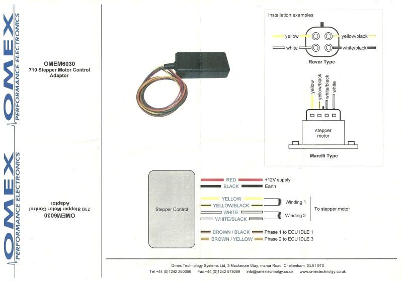
Heres the instructions
Here is the valve I am using
Now I think the instructions are abit vauge
I have decided to use FUEL3 and FUEL4 as my idle outputs
This is what i have changed on the calibration
I have turned off FUEL 4 as PWM
I have turnned off pwm idle not stepper
I have unselected idle PWM1 and 2 out to none
I have selected Idle1 stepper out to Fuel3
I have selected Idle2 stepper out to Fuel4
This has also changed the out idle1 and out idle2 further down the options list as expected
Now i have wired everything up temp as of the bottom diagram the first thing i have noticed is with the ignition off the box outputs a 12v feed all the time so this needs to be in to an ignition live rather that a terminal 30 but thats an easy fix
On my valve I have tested the pins and A and D are linked together and measure 50 ohms and B and C are linked together
again measure 50 so thats how I have wired it but wired up like this the valve just moved in and out very slightly no matter what the coolant duty cycle is set to, I have tried changing the inputs into the box from fuel 3 and 4 but this made no difference i also tried changing the polaraty through the valve windings but still no difference
I belive mine is a marrelli type valve as we mensioned previously and on the top of the instructions that is wired differently so I have tried to wire it up as shown now this time the valve moves out for about 10 secondsand stops untill you change the duty cycle then it moves again for 10 seconds, I then noticed if you touch the end of the valve it stops moving out and reverses but has not relation to the duty cycle.
I though it might be doing this as its not bolted in its housing so there is no stop, so I bolted it in to the housing but apears to be the same
Now do you think this is an obvious setting I have missed as im pritty stupid or the wiring or both?
I have attached the pwm calibration and the changes I have made
Hopefully it is somthing easy lol
I spoke to some one who has mapped a car with this valve on a different ecu and they said the responce rate sould be 102ms and the engine should idle at bout 40% duty cycle maybe 30% when up to temp
Thanks
Si
When I initially contacted Omex I got no responce and I was in abit of a rush so I continued to use my 2 wire bosch PWM idle valve this valve has now had it and wont work below 80% duty which we found out when mapping for a new inlet, so im back on to using the standard valve as my new inlet manifold is designed to use it.
It was setup with alot of ignition retard to get it to idle with the dead valve
I contacted Omex again asking about running the stepper motor on a 710 which i belive is very similar to the EM36?
They said it was no problem but I had to buy the 710 stepper motor adaptor which I assume is the duel H bridge setup that we previously talked about?
Heres the instructions
Here is the valve I am using
Now I think the instructions are abit vauge
I have decided to use FUEL3 and FUEL4 as my idle outputs
This is what i have changed on the calibration
I have turned off FUEL 4 as PWM
I have turnned off pwm idle not stepper
I have unselected idle PWM1 and 2 out to none
I have selected Idle1 stepper out to Fuel3
I have selected Idle2 stepper out to Fuel4
This has also changed the out idle1 and out idle2 further down the options list as expected
Now i have wired everything up temp as of the bottom diagram the first thing i have noticed is with the ignition off the box outputs a 12v feed all the time so this needs to be in to an ignition live rather that a terminal 30 but thats an easy fix
On my valve I have tested the pins and A and D are linked together and measure 50 ohms and B and C are linked together
again measure 50 so thats how I have wired it but wired up like this the valve just moved in and out very slightly no matter what the coolant duty cycle is set to, I have tried changing the inputs into the box from fuel 3 and 4 but this made no difference i also tried changing the polaraty through the valve windings but still no difference
I belive mine is a marrelli type valve as we mensioned previously and on the top of the instructions that is wired differently so I have tried to wire it up as shown now this time the valve moves out for about 10 secondsand stops untill you change the duty cycle then it moves again for 10 seconds, I then noticed if you touch the end of the valve it stops moving out and reverses but has not relation to the duty cycle.
I though it might be doing this as its not bolted in its housing so there is no stop, so I bolted it in to the housing but apears to be the same
Now do you think this is an obvious setting I have missed as im pritty stupid or the wiring or both?
I have attached the pwm calibration and the changes I have made
Hopefully it is somthing easy lol
I spoke to some one who has mapped a car with this valve on a different ecu and they said the responce rate sould be 102ms and the engine should idle at bout 40% duty cycle maybe 30% when up to temp
Thanks
Si
- Attachments
-
- AET new idle valve16.9.12.EM36 .V0.88.cal
- stepper
- (20.04KiB)Downloaded 2824 times
-
- AET 12.9.12.EM36 .V0.88.cal
- pwm
- (20.04KiB)Downloaded 2759 times
Re: Stepper motor
Welcome back Si,
I'll have a look at the calibrations and see what I can find. I might have to escalate this as it looks as if you are running with version 0.88. This shouldn't be a problem but I would like to confirm. Check back with you later.
BR
RickS
I'll have a look at the calibrations and see what I can find. I might have to escalate this as it looks as if you are running with version 0.88. This shouldn't be a problem but I would like to confirm. Check back with you later.
BR
RickS
Re: Stepper motor
OK Si...
Please check and adjust the two options 'Idle Duty Min' and 'Idle Duty Max'. There is not much difference between your two values, where I would expect the Min value to be about 1.25% and the Max about 96%-99%.
Among other things that need to be checked are the Idle Duty RPM table. This is a modifier, based on engine speed, looking to see if engine speed moves below the target idle, so acting as an anti-stall feature. Yours is 'flat-lined' at 0 which may need adjusting.
The idle is then fine-tuned and maintained by the feedback loop. Idle FB- max and Idle FB+ max are the feedback limits for the idle motor. The update rate of this feedback loop is set by Idle FB Rate and yours is currently set to 0 also. This would typically be 40ms with a stepper motor (200ms with a PWM device, for those reading this with one of those!).
Let's see what we get.!
BR
Rick
Re: Stepper motor
Nice one I will have a play about tonight see where we get
It does start at the moment just won't idle with out a bit of throttle I will let you know how I get on
Cheers
Si
It does start at the moment just won't idle with out a bit of throttle I will let you know how I get on
Cheers
Si
Re: Stepper motor
Just one quick one what's your oppinoin of how the valve should be wired?
Thanks
Si
Thanks
Si
Re: Stepper motor
The pairings of terminals on the idle motor can be found by multimeter continuity testing. If the valve goes the wrong way then you need to swap two of the wires in a pairing, so swap say the yellow and the yellow/black round.
The above info was gleaned from Omex. As the adapter is not GEMS kit, I have to bow to their superior knowledge..!
BR
Rick
The above info was gleaned from Omex. As the adapter is not GEMS kit, I have to bow to their superior knowledge..!
BR
Rick